My Daughter’s Nightstand

This week I finished a cabinet carpentry project started after Thanksgiving in 2014. It was a stretch of my skills, the first time building a project with full panel construction, where all the panels were solid wood. Except for the bottom of the drawer, the entire structure is made of solid wood. To control cost, the choice of wood was pine and fir. The legs and rails are made from fir, bought as a 2×8 and re-milled by me with a tablesaw and a thickness planer. The top, panels, drawer sides, and the rest are made from 1×6 lumber.

20150212-04

I finished the wood with fourteen thousand coats of milk paint, sanding between each one. The milk paint, in cream color, was top-coated with Danish oil finish because milk paint’s rough finish can stain easily. The green glass knobs came from a collection of my grandfather’s.

20150212-07

The early design planned for through tenons, to leave little exposed pegs. I had also intended to carve a sun-and-moon theme, later to be painted with bright colors.

nightstand_earlydraft

The panels were cut with the tablesaw. I mounted the panels in the tenoning jig. The runout was ridiculous. In spite of using a micrometer to true the tenoning jig, I had a very difficult time keeping the panel thickness constant. Next time I want to make panels I’ll buy a router jig for the purpose.

The drawer slides are also custom. I had roller suspended drawer slides, but neglected to design the drawer with enough clearance. The drawer front attaches to the drawer sides with hand-cut half-blind dovetails. I was pleased that my first attempt at half-blind dovetails worked out well.

20150212-11

The carcase is entirely mortise and tenon joints. I cut the tenons on the tablesaw wit the jig. In the entire cabinet the only metal fasteners are the clips that hold the table tops on, and the L-brackets that hold the draw slides on.

20150212-15

Dip Pens for the Backs of Photos

Quick Recommendation

Speedball B-5 nib

Rapidraw 3084-F or Reeves & Poole India Ink

The best solution I have found for writing on the back of plastic-coated photos, like those from Costco or most modern developers, is drafting ink. It would seem the inks are usually archival even though the paper is not. The writing is actually readable. When the ink is applied correctly it can be handled without risk of smearing in as little as a few minutes.

If you can’t stand my dip pen solution, more details are available here, where I recommended the Zig Millenium (blotted) or the Zig Photo Signature. The problem with drafting inks is that they cannot be applied with a Bic pen. The inks can by applied with technical pens or with dip pens. Technical pens are a delight, you can cap them—or rather you must cap them. They dry out and clog the pen if not cleaned properly. They are difficult to clean too.

When I’m writing on photos, I tend to do a batch at once, and then none for weeks. Filling a technical pen and cleaning it for an hour’s use is unsatisfying. The alternative to technical pens is the dip pen. Not all dip pens are created equally, or at least not for the same purpose. I had purchased a set of drawing nibs at the local hobby shop thinking I was all set. However, the drawing nibs left puddles of ink on, snagged, and spattered. The photo below shows the bumps and still-wet pools of ink when using some nibs and the smooth, even writing from others.

PensObliqueShot

Different nibs, obviously, perform differently. I thought perhaps different inks would too, and set about to test the pair. A well-performing ink-and-nib combination should

  • apply legibly without spatter
  • leave writing that does not smear after a few minutes
  • be convenient to use

Three simple criteria. Five inks. Six nibs.

Inks

  • Higgins Black Magic (probably latex based) (left)
  • Reeves & Poole India Ink (shellac based)
  • Rapidograph Ultradraw 3085-F (acrylic or latex based)
  • Rapidograph Rapidraw 3084-F (acrylic or latex based)
  • Rapidograph Universal 3080-F (acrylic or latex based)

Nibs

  • Hunt No. 104 (left)
  • Hunt No. 102
  • Hunt No. 56 School
  • Hunt No. 513EF
  • Speedball B-6
  • Speedball B-5

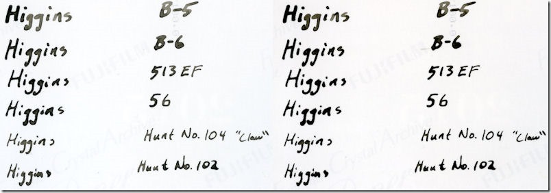
The test involved writing a the ink name and the nib name on the back of a Costco print. The paper is Fujifilm Crystal Archive, which seems to be a common print medium. I wrote each set on the back of the photos. About 24 hours later I scanned the images. After scanning I pressed a wadded facial tissue to the paper and wiped firmly from left to right. Each of the photos below shows the left side, before wiping, and the right side after wiping.

Higgins did not smear, but it did bleed. The detail zoom below is taken from the B-6 test, and the edges are fuzzy and bloomed. This ink, once my favorite, must now be relegated to the scrap.

higgins

higgins_detail


Reeves & Poole had very minor smearing with the No. 56 nib. It puddled horribly with the 513EF and the No. 56. It worked beautifully with the B-5, B-6. The No. 104 and the No. 102 both scraped the paper and left little puddles, but might be acceptable.

reevespoole


The Ultra 3085-F smeared with the No. 56. It was otherwise a stable ink. It performed well with the B-5 and the B-6 nib. The other nibs either puddled or scratched the photo. The detail below is the with the B-5 nib, and though the line is wide, the mark is very well behaved.

ultra_3085F

Ultra3085F_Detail


The 3084-F is darker than the 3085-F, and the ink is as well behaved in the B-5 and the B-6 nibs. I see no reason, based on these data, to prefer the 3085. I should have called it Rapid, not Ultra.

ultra_3084F


The 3080-F is dark, which is good, but the lines are very broad and poorly controlled.

ultra_3080F


Summary of Ink Performance

Ink Rank Comment
Rapidraw 3084-F 1 (tie)  
Reeves & Poole 1 (tie)  
Ultradraw 3085-F 3 Not very black
Universal 3080-F 4 Poor line control
Higgins Black Magic 5 Bleeding

Summary of Nib Performance

Nib Rank Comment
Speedball B-5 1 Well controlled, wide lines
Speedball B-6 2 Well controlled, but very slight blobbing
Hunt No. 102 3 Scratches, lines blob when crossing
Hunt No. 104 4 Scratches, lines blob badly when crossing
Hunt 513EF 5 Puddles badly
Hunt No. 56 School 6 Puddles extremely badly

The Electric Henhouse

chx_composite

This spring three lovely chicks joined our family, Betty, Penny, and Ginger. Ginger discovered her inner rooster in due time, and was rehomed—we are not zoned for the crowing half of the species. To protect the birds from freezing during our winter travels, and to let them out at the sunrise, they have been housed in the electric henhouse. At dawn and dusk the hens are released or secured by a linear actuator, locking in heat, wind and potential predators locked out.

Betty watching the installation of the electric henhouse.

betty_looking_at_install

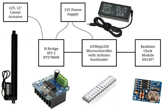
The heart of the electric henhouse is a bare-chip variant of the Arduino. It connects to a realtime clock with battery backup to get the time. The time, in turn, is used with calculated sunrise and sunset so the door opens at sunrise and closes shortly after sunset when the birds have settled down for the night. The ATMega runs at 5 volts, and so a dual H-bridge is used to provide the linear actuator with the power it needs.

parts_overview

The overall code architecture is straightforward, every second the processor checks the time. If the time is between the sunrise and sunset, tell the motor to open, otherwise close. The motor module maintains a state so that it won’t try to open an open door. The linear actuator is cleverly designed, it won’t strain to open when it is always open and it won’t close when all the way closed.

The only code module with much complexity is the sunrise and sunset calculation, which is an approximation based on a US Naval Observatory code, with only minor modifications. I tested it by running the calculation over a series of days throughout the year and comparing with published almanac.

I purchased two separate FTDI USB-to-serial chips to program the bare ATMega chip, and was unable to get either of them working. I followed programming instructions similar to those here, and those worked every time.

The linear actuator is visible at the top. It slides the door (currently open).

20141221-0067

You can get the code on GitHub.

3D-Printer and Your Coffee Grinder

20141101-76

Two weeks ago I acquired a 3D printer; specifically the Printrbot Simple Metal Kit and, after some warranty help, it’s printing well. The first thing I printed was the fan shroud for the 3D printer itself, as recommended by Printrbot, but the next things were for my own design. I printed a set of three sieves, to fulfill my long-time dream of quantifying the performance of coffee mills.

For those of you who read my coffee blog posts years ago, I was frustrated because nobody quantifies the grind performance. Vendors and coffee pundits are happy to talk about the merits of a conical burr grinder or fret about the cheap blade grinder you got from your lost year with Gevalia. Quantifying grinder performance should be pretty straightforward. Take a set of sieves and sort the grinds by size, the more consistent grinders will produce more grounds in a narrow range of sizes. Spoiler: I have only measured my whirling blade grinder so far, not my Capresso burr grinder or any of the commercial grinders.

The printed sieves are just cylinders with a printed mesh bottom. They don’t stack well, since I used too little taper. My finest one had holes so small that it plugged with the finest coffee dust, so there is more to do in the sieve design. Nevertheless, I started with the mesh from Thingiverse, and added 15 mm of wall height. When I get a version of these that stacks I’ll post the design to the Thingiverse too.

sieve_screenshot

I arranged the sieves in a stack and shook. The sieves clogged almost immediately, so I took a small brush and worked the from the top layer down until I had good separation.

sieving_illustration

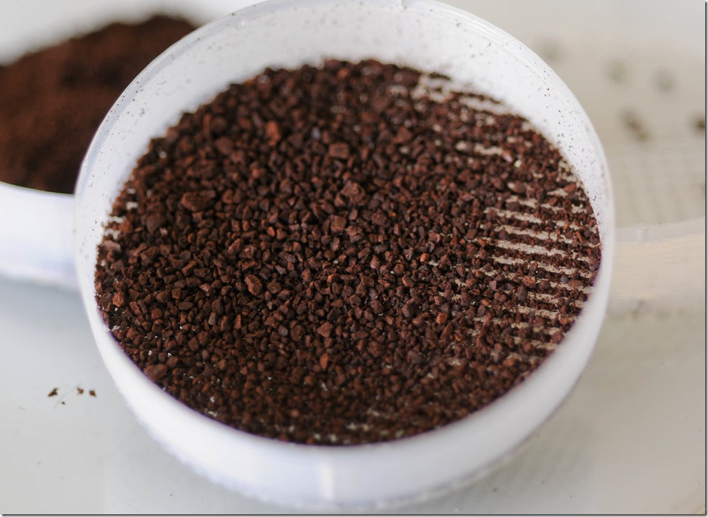
The results, in the following picture, show that almost no particles were larger than my largest mesh, less than half were larger than my medium mesh, and the rest were larger than my fine mesh.

20141101-66

So what are the mesh sizes? I took macro photos of the meshes and then measured them optically—you know, counted pixels. The composite photo below shows the basic idea, and below that is a zoomed-in version of the medium sieve.

composite_sieve

The medium sieve is made from “threads”, where each “thread” is two passes with the extruder head. It should be possible to do a single extruder path, but I have not yet tuned the OpenSCAD file to get a consistent result.

20141101-84_closecrop

Mesh Cell Diagonal Coffee Percent
Coarse 2.5 mm <0.1 g 0%
Medium 1.4 mm 1.0 g 28%
Fine 0.48 mm 2.6 g 72%
  fall through <0.1 g 0%

Whether grind consistency can actually be identified by a taster in a blind test is an open, and wonderful, question. Happy brewing!

The Giving Tree and An Arduino Clock

When we bought our house we hired an electrician to install ceiling fans and lights. He worked, worked, and worked. My illusions of electrician’s work dissolved. Their work is a great deal more like laying bricks than solving equations. Oddly, the truth for electricians is also the truth for electronics.

Nearly two years after starting, more than 18~months after finishing the electronics, source code, and cardboard mock-up I finally finished my clock. I have recreated—nay, improved upon—the greatest alarm clock I have ever owned.

20120804-Pano-Backyard2

In some ways my clock was started about thirty years ago, when some foresighted person planted a lovely little apple tree in what is now my back yard. The lovely little apple tree was a gorgeous mature giant shady apple tree until the spring of 2012. The spring came warm and early but also trisected by two severe cold spells. The frost killed several of my trees major limbs, and may eventually kill the tree.

One of the major limbs became firewood. Then one of the firewood logs became boards, and finally one of the boards became the main faces of the clock. Making a board from firewood is, no doubt, ancient. For me it was a new experience with old techniques. I used a hand powered bow saw, affixed the firewood in the vice, and ripped boards by hand. It is a tiresome process and the boards were not machined to the parallel faces you get in dimensioned lumber. No matter, hand planes helped me get one face smooth and flat. I marked a constant thickness, flipped the board over, and planed the uneven face. The finished board was smooth, clean, and beautifully figured.

The original vision for the box of the clock had hand-cut dovetails visible on the front. However, the apple wood was unsupportive. It was brittle, and prone to fracturing on detail peices. It was also almost too small. The cherry boards I selected for the sides were not long enough to dovetail join the front and back.

clock_hand_drawing

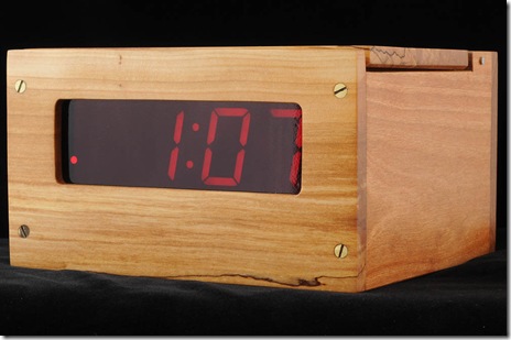
The final result is lovely to me. It has a lid so the interface is not visible on the bedside, and the lid showcases the figure of the apple wood. The display is a simple red that does not keep me awake at night. The plain box design weighs enough to keep from migrating around the nightstand, and the interface is actually good.
20140817-0620140817-0120140817-0520140817-02-2

Design and Use

I set out to imitate the functions of my beloved but deceased clock, see Behold! A number pad. I started the design with a set of use cases, Set Time, Set Alarm, Turn on Alarm, and Turn off Alarm. The notes below are from the original design before I bought the first part, with no edits but formatting.

Set Time

User opens decorative lid. User sets mode switch “set time” mode. The display is turned to current time. User enters numbers starting with most significant digit, in 24 hour time format. After entering the first number, only that digit is displayed.

If user enters a mistake, he hits “clear (#),” and the process restarts at “user enters numbers”. Clear: display is blanked. To keep the setting, user leaves the “set time” mode. On error, the time remains unchanged. Error conditions are:

  • User exits "set time" mode without entering a new time at all.
  • User exits "set time" mode without entering a valid time.

Set Alarm

Same as “Set Time,” but using “set alarm” mode.

Turn on Alarm

User turns on alarm. Display flashes time the alarm is set for about 5 seconds. Display resumes normal operation. The “alarm on” LED lights. When the time reaches the set alarm time, a beeper will sound. The beeper will sound until the alarm is shut off.

Turn off Alarm

Alarm LED is turned off. If the alarm is currently beeping, the beeping ceases.

Electronics Design

I ended up with a Sparkfun keypad, and care of Andrew’s diligent work I was able to configure the Arduino microprocessor to use the keypad almost painlessly. I arranged the pinout as follows:

Pin Use
0 not available
1 not available
2 keypad 0
3 keypad 1
4 keypad 2
5 keypad 3
6 keypad 4
7 keypad 5
8 keypad 6
9 alarm on/off switch
10 alarm tone (PWM)
11  
12  
13  
14 (A0)  
15 (A1) display brightness potentiometer
16 (A2)  
17 (A3) mode switch (3-state) alarm/time
18 (A4) i2c – display and realtime clock
19 (A5) i2c – display and realtime clock

Pin A3 was used for analog read to determine the state of a simple resistor network. Switching the mode switch changes the resistors in a voltage divider. I designed this before I learned about the Arduino’s internal pull-up resistor, so the analog electronics are more difficult than I would make them today.

In case anyone wants it, the code is here also.


#include <Wire.h>
#include "Adafruit_LEDBackpack.h"
#include "Adafruit_GFX.h"
#include <Keypad.h>
#include "RTClib.h"

RTC_DS1307 RTC;
DateTime now;

#define PIN_ALARMSWITCH 9
#define PIN_ALARMTONE 10
#define PIN_MODE3STATE A3

#define PIN_BRIGHTNESSPOT A2 // on the left

#define COLON 2
#define PM 8
#define ALARM 4
#define EXTRA 16

int brightness( void){
  // the analog reading is between 0 and 1024, so divide by 64 to get the
  // values between 0 and 15
  return analogRead( PIN_BRIGHTNESSPOT) >> 6; 
}

class ClockDisp : public Adafruit_7segment {
  uint8_t alarmOn;
  uint8_t pmOn;
  uint8_t colonOn;
  public:
  void writeState( void);
  void alarm( bool);
  void pm( bool);
  void colon( bool);
  void toggleColon( void);
  void printTime( DateTime now);
  void blank( void);
};

void ClockDisp::blank( void){
  print(10000, DEC);
  writeDisplay();
}

void ClockDisp::writeState( void){
  writeDigitRaw( 2, alarmOn | pmOn | colonOn );
  writeDisplay();
}

void ClockDisp::alarm( bool newState ){
  if( newState){
    alarmOn = 4;
  }else{
    alarmOn = 0;
  }
  writeState();
}

void ClockDisp::pm( bool newState){
  if( newState){
    pmOn = 8;
  }else{
    pmOn = 0;
  }
  writeState();
}

void ClockDisp::colon( bool newState){
  if( newState){
    colonOn = 2;
  }else{
    colonOn = 0;
  }
  writeState();
}

void ClockDisp::toggleColon( void){
  colonOn ^= 2;
  writeState();
}

void ClockDisp::printTime( DateTime now){
  //DateTime now = RTC.now();
  int hour = now.hour();
  if( hour > 12){
    pmOn = 8;
    hour %= 12;
  } else{
   pmOn = 0;
   if( hour == 0) hour = 12;
  }
  int decimalTime = hour * 100 + now.minute();
  print( decimalTime);
  writeState();
}        
        
const byte ROWS = 4; //four rows
const byte COLS = 3; //four columns
//define the cymbols on the buttons of the keypads
char keys[ROWS][COLS] = {
  {'1','2','3'},
  {'4','5','6'},
  {'7','8','9'},
  {'*','0','#'}
};
byte rowPins[ROWS] = {7,2,3,5}; //connect to the row pinouts of the keypad
byte colPins[COLS] = {6,8,4}; //connect to the column pinouts of the keypad

//initialize an instance of class NewKeypad
Keypad customKeypad = Keypad( makeKeymap(keys), rowPins, colPins, ROWS, COLS); 

//Adafruit_7segment matrix = Adafruit_7segment();
ClockDisp clockDisp = ClockDisp();
int alarmNum = -1;
bool isAlarming = 0;
bool hasAlarmed = 0;

void setup(){

  Serial.begin(9600);
  Serial.println("Clockit");
  
  Wire.begin();
  RTC.begin();

  if (! RTC.isrunning()) {
    Serial.println("RTC is NOT running!");
    // following line sets the RTC to the date & time this 
    // sketch was compiled, except on Mac.
    RTC.adjust(DateTime(__DATE__, __TIME__));
  }
  
  clockDisp.begin(0x70);
  clockDisp.setBrightness( 10);
  
  clockDisp.blank();
}

void loop() {
  Serial.println("Top of loop");
  now = RTC.now();
  Serial.print("Brightness pin: ");
  Serial.println( analogRead( PIN_BRIGHTNESSPOT));
  clockDisp.setBrightness( brightness());
  // Print the time, and update the colon
  Serial.print("Time decimal: "); Serial.println( now.hour() * 100 + now.minute());
  clockDisp.printTime( now);
  if( millis()%1000 < 500){
    clockDisp.colon(1);
  }else{
    clockDisp.colon(0);
  }
  delay( 20);
  
  /* The alarm function is actually a little bit complicated. It is
  easy to test if the current time is equal to the alarm time. We 
  want the alarm to start beeping and not to stop until the switch 
  is thrown. However, if we immediately turned the switch back on,
  the current time would still exceed the alarm time, and it would
  start beebing. Therefore, I created the hasAlarmed variable, which
  records that the alarm has gone off. hasAlarmed will reset to FALSE
  when the time is less than the alarm time, indicated that we've come
  around the clock again.
  */
  
  if( digitalRead( PIN_ALARMSWITCH)){
    clockDisp.alarm( 1);
    if( isAlarming){
      if( millis()%1000 < 500){
        tone( PIN_ALARMTONE, 1000);
      }else{
        noTone( PIN_ALARMTONE);
      }
    } else if( hasAlarmed){
      if( (now.hour() * 100 + now.minute()) < alarmNum ){
        hasAlarmed = 0;
      }
    } else {
      // See if we need to turn on the alarm
      if((now.hour() * 100 + now.minute()) == alarmNum){
        isAlarming = 1;
      }
    }
  }else if( isAlarming){
    clockDisp.alarm( 0);
    noTone( PIN_ALARMTONE);
    isAlarming = 0;
    hasAlarmed = 1;
  }else{
    clockDisp.alarm(0);
  }


   // Contol of setting state switch
   int mode = analogRead( A3);
   Serial.print("Mode reading: "); Serial.println( mode);
   if( mode > 900 ){ // set the time
    Serial.println("Setting the time");
    // blank the display  
    clockDisp.blank();
    int numDigits = 0;
    int timeNum = 0;
    
    while( analogRead(A3) > 900){
      // wait for keys, display them, check state
      // wait for entry of time
      char customKey = customKeypad.getKey();
      if( customKey > 0){
        if( numDigits > 0){
          timeNum = timeNum*10 + (int)(customKey - '0');
        }else{
          timeNum = (int)(customKey - '0');
        }  
        numDigits ++;  
        
        clockDisp.print( timeNum);
        clockDisp.writeDisplay();
      }
    }
    // Test to see if we got a valid time:
    if( (timeNum < 2500) && (timeNum > 0)){
      RTC.adjust( DateTime( now.year(), now.month(), now.day(),
              timeNum / 100, timeNum%100, 0));
    }else{
      // An error, flash bars at the user
      clockDisp.print( 10000);
      clockDisp.writeDisplay();
      delay( 300);
    }
  }else if( mode > 490){ // state 2
    clockDisp.print( alarmNum);
    clockDisp.writeDisplay();
    int numDigits = 0;
   
    while( 1 ){
      int ar = analogRead( A3);
      if( (ar < 490) || (ar > 900)) break;

      // wait for keys, display them, check state
      // wait for entry of time
      char customKey = customKeypad.getKey();
      if( customKey > 0){
        if( numDigits > 0){
          alarmNum = alarmNum*10 + (int)(customKey - '0');
        }else{
          alarmNum = (int)(customKey - '0');
        }  
        numDigits ++;  
        
        //clockDisp.print( (int)(customKey - '0'));
        clockDisp.print( alarmNum);
        clockDisp.writeDisplay();
      }
    }
    // Test to see if we got a valid time:
    if( (alarmNum >= 2500) || (alarmNum < 0)){
      // Invalid time entered, flash error bars at user
      clockDisp.print( 10000);
      clockDisp.writeDisplay();
      delay( 300);
    } else{
      hasAlarmed = 0;
    }
  } 
}

int getDecimalTime(){
  DateTime now = RTC.now();
  int decimalTime = now.hour() * 100 + now.minute();
  return decimalTime;
}

Wiring an Arduino to a Five-state Guitar Switch

I am rebuilding my Arduino-based data collection system. Named the RIMU for some long-forgotten and pointless acronym. My old one used a momentary switch—a button—to change which sensor is displayed on the LCD. It is awful because if the Arduino is busy when you push the switch then nothing happens. I’m fixing it with a 5-position switch sold for changing the pickup combinations on electric guitars.

I was thinking about some really good machine interfaces, and some really bad. I walked about the house with a camera. Below are some photo collections of good and bad interfaces around the house.

interface_montage

Good interfaces control devices unambiguously with touch. You should not have to look at the device to know what mode you have changed it to. Really great interfaces, like a light switch, reveal their state by touch.

My switch is almost as good as a light switch. With five states it is hard to tell which state it is in by feeling its position; however, it is easy to change state. Even better, its position is an absolute indication of its state. There is no issue of the Arduino being busy when the state changes, because the state is fixed by the switch. It is not toggled by some transient state.

I bought my switch from Sparkfun, and also lifted this product image from them.

5way_product_image_10541-01

If you can find old rotary switches with detents you can use the analog read function of the Arduino to get all the states with a single pin. In this case, though, I will use three pins to represent the states. I believe it is possible to configure this switch with a  few resistors to represent all its states with a single analog input, but it is more complex to figure out and I am not short on pins. My definition of pins. The ones with wires are the only ones I need to use.

switchphoto_with_pins

With just three digital inputs, the Arduino can read all five switch states. The Arduino’s microprocessor includes built-in pull-up resistors. These are easy to use, but a little bit confusing. A pull-up resistor means that if the pin is not attached to anything, the Arduino will read the pin high.
5state

In the following table I show a Y to indicate how the switch is connected internally. However the ABC column shows what you would read from the pins in the Arduino.

Pos 1 2 3 ABC
1 Y 110 6
2 Y Y 100 4
3 Y 101 5
4 Y Y 001 1
5 Y 011 3
// Define the spins to read the switch
#define pinSwitch1 2 
#define pinSwitch2 3 
#define pinSwitch3 4

unsigned char switchState( void){
  unsigned char state=0, in;
  
  in = digitalRead( pinSwitch1);
  state |= in << 2;
  in = digitalRead( pinSwitch2);
  state |= in << 1;
  in = digitalRead( pinSwitch3);
  state |= in;
  
  switch( state){
    case 6:
    return 1;
    case 4:
    return 2;
    case 5:
    return 3;
    case 1:
    return 4;
    case 3:
    return 5;
  };
  return 0;
}
    
void setup( void){
  pinMode( pinSwitch1, INPUT);
  pinMode( pinSwitch2, INPUT);
  pinMode( pinSwitch3, INPUT);
  digitalWrite( pinSwitch1, HIGH);
  digitalWrite( pinSwitch2, HIGH);
  digitalWrite( pinSwitch3, HIGH);
  Serial.begin( 57600);
  Serial.println( 'Started');
}

void loop( void){
  Serial.print( "Switch: ");
  Serial.println( switchState());
  Serial.print( " ");
  Serial.print( digitalRead(pinSwitch3));
  Serial.print( " ");
  Serial.print( digitalRead( pinSwitch2));
  Serial.print( " ");
  Serial.print( digitalRead( pinSwitch1));
  Serial.print( " ");
  delay( 1000);
}

Chutes and Ladders Infinite Loop

I play Chutes and Ladders with my kids sometimes. It isn’t a game of skill. Many months ago I was involved in a game that went on and on and on. As soon as someone would get close to the end he or she would land on a chute and be shunted nearly back to start.

I was left wondering just how long a game would last. So this week my son and I implemented a simulator in Python to calculate how long any one person’s game would last. Each person’s play is independent in Chutes and Ladders, the characters do not interact. Therefore, simulating an entire game is almost as easy as simulating a single player’s experience.

First, the board is 100 cells long and the spinner gives you a value between 1 and 6, just like rolling a die. A fair die will have an average roll of 3.5, so on average it would take about 100/3.5 = 28.6 turns to finish a game if there were no chutes or ladders. The histogram of game length without chutes and ladders is below. The longest plausible game is about 35 turns in this scenario and the average is 28.6 turns, estimated from 10,000 random trials.

chuteshist_nochutes

The addition of chutes and ladders stretches the histogram radically. Instead of the longest single-person game being about 35 turns, it is now over 200 turns. Fortunately, a 200-turn game is not very likely. Surprisingly the average is not a hundred million years. At 30.8 turns the average game with chutes and ladders is only a little longer than the average game without.

chuteshist

Pretty cool.

 
import random 
import pylab as plt
import numpy as np
d = {}
for i in range(1, 101):
    d[i] = i

cl = {1: 38,
     4: 14,
     9: 31,
     16: 6,
     21: 42,
     28: 84,
     36: 44,
     48: 26,
     49: 11,
     51: 67,
     56: 53,
     62: 19,
     64: 60,
     71: 91,
     80: 100,
     87: 24,
     93: 73,
     95: 75,
     98: 78}
d.update(cl)
numturnsa = []
for t in range(10000):
    numturns = 0
    pos = 0

    while True:
        numturns += 1
        pos += random.randint(1,7)
        if pos &gt; 100:
            break
        # To "play" without chutes and ladders, comment out the next line.
        pos = d[pos]
    numturnsa.append(numturns)

plt.figure(figsize=(5,3))
plt.subplots_adjust( .13, .15, .95, .97)
plt.hist(numturnsa, 60)
plt.xlabel("Number of turns")
plt.ylabel("Count")
plt.savefig("chuteshist_nochutes.png", dpi=200)
numturnsa = np.array(numturnsa, dtype="f")
print "The average number of turns is",np.mean(numturnsa)

Monsoon

In the desert it almost never rains. I know, you know. When I lived in upstate New York, in my foolish youth, I bought a motorcycle in the beginning of April. I was anxious to learn to ride. Too bad, because it rained every day for an entire month. Now I live in New Mexico. Two years ago we had not one drop between the end of December and July.

Where you live the weather turns with a unique step. Here, the summer breaks in July when the monsoon comes. Moist air from the Gulf of California and the Gulf of Mexico flow north over the state and give rise to afternoon thunderstorms. It is the most beautiful weather of the year here. The clouds rise miles—literally—into the sky and continuously billow in fractal glory.

Last week I configured my Raspberry Pi computer with its PiCam to take time-lapse video out my back window. The view is to the east over the Sandia Mountains. I took pictures about every six seconds from 10:30 am until dark, around 8:30 pm. The whole day compressed into four and a half minutes. The best video was from July 14, others are below.

It is hard to understand the desert if you have never lived in one. In the picture below you can see what it would be like if Leeds were in Albuquerque. A nation that ruled the world for a few hundred years fits comfortably in the desert southwest.composite

The rest of the videos I created are here, with the most interesting at the top.

July 11

July 13

July 8

July 7

July 10

July 16

July 15

The Spiraling Shape

The Spiraling Shape will make you go insane
Everyone wants to see that groovy thing

–They Might Be Giants

The chambered nautilus is sometimes called a living fossil. It is the closest living relative of the ammonoids, and cross sections of its shell are familiar to every adult in the western world. Most kinds of ammonoids lived a long time ago. They started appearing in our Devonian strata around 415 million years ago. Pretty cool, since modern humans have been around 0.195 million years. If you consider the chambered nautilus close enough, then you might say that these critters have been around 2000 times longer than humans. That is real staying power.

In June my wife and I visited San Francisco for a vacation. A delightful city for touring because it has such a mix of old turn of the 20th century buildings, awesome bridges, a cool sea breeze, great parks and museums, shopping, cultural diversity, and enough hipsters to feed Cthulhu for an eon. Unless someone can find a more suitable use for hipsters.

In Chinatown we saw all the usual junk. But there was also a rock shop that had a nice assortment of cross-sectioned fossil ammonoids or nautiloids. I dug through and looked for one with the most open inner spirals. And here it is.

Nauty

I scanned it at absurdly high resolution, the largest diameter is 1.6 inches. The construction of the nautiloid is fascinating. The spiral is logarithmic, as you can find asserted all over the web. Of course, in my entire life I have never seen anyone actually measure the spiral and show its logarthmic nature. But it looks like it a logarithmic spiral.

The structure is self-similar. It is hard to tell how big this little shell is because it would like basically the same to your eye at ten times the size. I love that: fractal without fragmentation.  The creature, I suppose, could grow large just by repeating the same basic step—grow a new chamber. The genetic code to scale up must have been quite an innovation, evolutionarily speaking.

g_apng

Distilling the spiral of the shell to its simplest shape shows awesome, but not perfect, consistency.

g_b

I have never seen a discussion of how the maximum and minimum buoyancy of the creature might have changed as it grew. You can bet that there is a clever relationship between the mass of the cephalopod’s body, the mass of its shell, and the volume of each successive  chamber, at least for those that can move vertically. Seafloor-dwelling species might be marked by a faster-opening spiral that keeps their shell from rising. Why is that a safe bet?

I understand that the nautilus spends the day deep in the ocean, and rises near the surface to hunt at night. They control their depth by pumping water in and out of their shell chambers. A nautilus’ chambers are connected by a little hole, and I can’t see any holes between chambers in my fossil so maybe mine wandered about on the seafloor or floated at a constant depth.

I measured my trace for the distance between spirals. I divided them all by the smallest one and produced the measurements

1 1.3 2.9 5.6 12 25 49
g_c
And this spiral does indeed show logarithmic growth. The plot shows the plot of the natural logarithm of the same measurements. Its consistency is so very, very good. I suppose that’s what makes the shell so pretty.
plot
 

Ear Tips for Noise Canceling Headphones

Most people have never tried in-ear headphones. They get ear wax on them, so to don’t share well. Wearing them on stage, musicians can hear their own instruments without going deaf. Since musicians use them for performance in-ear headphones are also called monitors, just like the speakers that point toward the band from the front of the stage.

Distraction, from airplane noise, office noise, maybe your own keyboard, annoys. Three headphones solve the problem. Most famously, Bose’s active noise canceling Quiet Comfort line and similar products by other makers. Passive noise reduction from sealed over-ear headphones is about 10 dB. In-ear monitors offer passive isolation between 20 and 30 dB.

I demoed the Bose phones years ago, and they hissed with the noise cancellation on. The sound quality was neither exceptional nor awful, but was poor for a $300 price. World-class sound quality is available from makers like Etymotic and Westone with in-ear monitors that provide as much isolation as active noise canceling models.

But in-ear monitors have one major drawback, they go in your ear canal. That means that they can get gross with ear wax, can be painful or itchy, and they can wear out. In my nine years using in-ear monitors I only ever found the foam tips from the manufacturer comfortable. The three-flange silicon tips isolate amazingly, but itch like fire after twenty minutes and hurt like a drill after sixty. The foam tips are comfortable, almost as isolating as the three-flange tips, but cannot be fully cleaned and wear out after three months.

tip_catalog

The most recent time I wore out a pair of foam tips, I decided it was time to look at the alternatives. I hoped to find, ideally, a comfortable silicon tip with the isolation of the foam tips or an inexpensively replaceable foam tip. It seems to be sort of a niche market, and I failed to find any useful comparisons on the web. So, I did my own.

I purchased a sizing kit from Westone, another from Monster, and a pack of the universally-liked Comply foam tips. Testing included a few leftover tips from the headphone’s original purchase, and I included those in the comparison.

I evaluated each tip for fit, seal, pain, itching, sound quality, isolation, and microphonics. Fit, seal, sound quality, and isolation are all related. With in-ear phones a poor seal means poor isolation and poor bass response and poor sound quality. Good fit depends on having the correct size tip for your ear. Medium tips from most manufacturers fit my ears well. The calipers in the picture below show a base diameter around 0.465 in (1.18 cm).

comply-tip-size

Most of the tip designs are old. Grubby among my grandfather’s shooting supplies, foam and triple flange tips were familiar to me twenty-five years ago. Recently Westone introduced a single-flange tip focusing on good seal and comfort. These, along with other single-flange tips, suffer from awful microphonics. When cables rub against anything, like your arm as you move the mouse, the motion travels along the cables and makes loud popping noises. Single-flange tips have the worst microphonics.

The best overall tips for me are Comply’s T-100 PLT medium foam tip. They cause no pain or itching, seal great and offer very good isolation, have low microphonics, and sound very good. Like all foam tips, they will wear out in three months and get waxy and gross. And they are neither the most isolating nor the quietest.

The best sounding tips are the Westone silicone three-flange tips, which offer by far the best isolation and by a small margin the best sound. After twenty minutes they also offer crushing pain and infernal itching. The three-flange tips have a place in my kit, but I don’t use them long.

Westone’s single flange tips are silicone, and are comfortable. My notes describe the itching from Westone’s silicone three-flange tip as extreme. After that, finding any silicone tip bearable was a surprise. The Westone Star tip is comfortable. It has poor microphonics, and poor isolation; it has no place on an airplane or a noisy office. On the other hand, Star Tips are cleanable and provide some isolation, so they are candidates for the gym. These also have a place in my kit.

The rest of the tips are unsurprising. Everything from Monster had poor isolation and had distracting microphonics due to a poor design. All of the other fitting foam tips are acceptable, but none are as good as Comply’s. All the other silicone tips are unacceptable for me, too painful, too itchy, too microphonic, and sound too poor. The results for all tips that fit reasonably well are in the table at the end.

I tested these tips with an hour-long playlist from mixed genre, seven songs in all. It starts with D. Barenboim/Berliner Staatskapelle recording of Beethoven’s Symphony 9, included to show dynamic range of symphonic instrumentation. The next two songs have typical mid-pitch-heavy pop songs including Adele’s One and Only off her album 21, and Erica Badu’s Four Leaf Clover from Baduism. Next, Erica Badu’s Rimshot shows the performance with an extreme deep bass opening line. Sweet Jane from the Cowboy Junkies is more typical pop. A mid-heavy but delicate sound and detailed sound from Miloš Karadaglić’s album Mediterráneo with his performance of Granados’ Danzas españolas, Op.-No. 2 Oriental. Finally, a very detailed song from Rush, The Necromancer off their album Caress of Steel has shown the weaknesses of many sound systems. I chose an hour-long playlist because in my experience in-ear monitors often lead to such itching and pain in the ears that I want to claw them out of ears screaming after forty minutes.

Monster produced the only foam tips I avoid. To fit my earphones you put the tiny red rubber rings around the earphone and then slide the tip over the top. The result was poor isolation and poor microphonics.

monster-tip

Tip

Size

Fit

Seal

Sound

Iso.

Mic.

Pain

Itch

Westone Classic Foam

Med

G

G

G

G

G

G

G

Westone Silicone White 3-flange

G

E

E

E

G

M

VP

Comply Foam T-100 PLT

Med

G

G

VG

VG

VG

VG

VG

Westone Star Silicone Black 1-flange

Med

G

G

VG

P

P

VG

VG

Westone Classic Foam

Med-Long

G

G

G

G

G

VG

G

Westone Truefit+ Foam

Med

G

G

G

G

G

G

VG

Westone Silicone Black 1-flange

Med

G

G

G

G

P

G

G

Westone Star Silicon Black 1-flange

Med-Long

G

G

VG

P

P

P

G

Weston Truefit+ Foam

Med-Long

G

VG

G

VG

G

G

G

Westone Silicone Clear 1-flange

Med

G

P

P

P

P

P

G

Westone Classic Foam

Small-Long

G

P

P

P

G

VG

G

Monster Foam

Med

G

G

G

P

P

G

G

My wife put me onto Bloglovin for those who follow with an aggregator. If you like, Follow my blog with Bloglovin. Finally, I have had no contact with the makers of these products, and I wasn’t compensated or paid in any way. Quite the contrary, I bought all the equipment reviewed here.