My Daughter’s Nightstand

This week I finished a cabinet carpentry project started after Thanksgiving in 2014. It was a stretch of my skills, the first time building a project with full panel construction, where all the panels were solid wood. Except for the bottom of the drawer, the entire structure is made of solid wood. To control cost, the choice of wood was pine and fir. The legs and rails are made from fir, bought as a 2×8 and re-milled by me with a tablesaw and a thickness planer. The top, panels, drawer sides, and the rest are made from 1×6 lumber.

20150212-04

I finished the wood with fourteen thousand coats of milk paint, sanding between each one. The milk paint, in cream color, was top-coated with Danish oil finish because milk paint’s rough finish can stain easily. The green glass knobs came from a collection of my grandfather’s.

20150212-07

The early design planned for through tenons, to leave little exposed pegs. I had also intended to carve a sun-and-moon theme, later to be painted with bright colors.

nightstand_earlydraft

The panels were cut with the tablesaw. I mounted the panels in the tenoning jig. The runout was ridiculous. In spite of using a micrometer to true the tenoning jig, I had a very difficult time keeping the panel thickness constant. Next time I want to make panels I’ll buy a router jig for the purpose.

The drawer slides are also custom. I had roller suspended drawer slides, but neglected to design the drawer with enough clearance. The drawer front attaches to the drawer sides with hand-cut half-blind dovetails. I was pleased that my first attempt at half-blind dovetails worked out well.

20150212-11

The carcase is entirely mortise and tenon joints. I cut the tenons on the tablesaw wit the jig. In the entire cabinet the only metal fasteners are the clips that hold the table tops on, and the L-brackets that hold the draw slides on.

20150212-15

3D-Printer and Your Coffee Grinder

20141101-76

Two weeks ago I acquired a 3D printer; specifically the Printrbot Simple Metal Kit and, after some warranty help, it’s printing well. The first thing I printed was the fan shroud for the 3D printer itself, as recommended by Printrbot, but the next things were for my own design. I printed a set of three sieves, to fulfill my long-time dream of quantifying the performance of coffee mills.

For those of you who read my coffee blog posts years ago, I was frustrated because nobody quantifies the grind performance. Vendors and coffee pundits are happy to talk about the merits of a conical burr grinder or fret about the cheap blade grinder you got from your lost year with Gevalia. Quantifying grinder performance should be pretty straightforward. Take a set of sieves and sort the grinds by size, the more consistent grinders will produce more grounds in a narrow range of sizes. Spoiler: I have only measured my whirling blade grinder so far, not my Capresso burr grinder or any of the commercial grinders.

The printed sieves are just cylinders with a printed mesh bottom. They don’t stack well, since I used too little taper. My finest one had holes so small that it plugged with the finest coffee dust, so there is more to do in the sieve design. Nevertheless, I started with the mesh from Thingiverse, and added 15 mm of wall height. When I get a version of these that stacks I’ll post the design to the Thingiverse too.

sieve_screenshot

I arranged the sieves in a stack and shook. The sieves clogged almost immediately, so I took a small brush and worked the from the top layer down until I had good separation.

sieving_illustration

The results, in the following picture, show that almost no particles were larger than my largest mesh, less than half were larger than my medium mesh, and the rest were larger than my fine mesh.

20141101-66

So what are the mesh sizes? I took macro photos of the meshes and then measured them optically—you know, counted pixels. The composite photo below shows the basic idea, and below that is a zoomed-in version of the medium sieve.

composite_sieve

The medium sieve is made from “threads”, where each “thread” is two passes with the extruder head. It should be possible to do a single extruder path, but I have not yet tuned the OpenSCAD file to get a consistent result.

20141101-84_closecrop

Mesh Cell Diagonal Coffee Percent
Coarse 2.5 mm <0.1 g 0%
Medium 1.4 mm 1.0 g 28%
Fine 0.48 mm 2.6 g 72%
  fall through <0.1 g 0%

Whether grind consistency can actually be identified by a taster in a blind test is an open, and wonderful, question. Happy brewing!

The Giving Tree and An Arduino Clock

When we bought our house we hired an electrician to install ceiling fans and lights. He worked, worked, and worked. My illusions of electrician’s work dissolved. Their work is a great deal more like laying bricks than solving equations. Oddly, the truth for electricians is also the truth for electronics.

Nearly two years after starting, more than 18~months after finishing the electronics, source code, and cardboard mock-up I finally finished my clock. I have recreated—nay, improved upon—the greatest alarm clock I have ever owned.

20120804-Pano-Backyard2

In some ways my clock was started about thirty years ago, when some foresighted person planted a lovely little apple tree in what is now my back yard. The lovely little apple tree was a gorgeous mature giant shady apple tree until the spring of 2012. The spring came warm and early but also trisected by two severe cold spells. The frost killed several of my trees major limbs, and may eventually kill the tree.

One of the major limbs became firewood. Then one of the firewood logs became boards, and finally one of the boards became the main faces of the clock. Making a board from firewood is, no doubt, ancient. For me it was a new experience with old techniques. I used a hand powered bow saw, affixed the firewood in the vice, and ripped boards by hand. It is a tiresome process and the boards were not machined to the parallel faces you get in dimensioned lumber. No matter, hand planes helped me get one face smooth and flat. I marked a constant thickness, flipped the board over, and planed the uneven face. The finished board was smooth, clean, and beautifully figured.

The original vision for the box of the clock had hand-cut dovetails visible on the front. However, the apple wood was unsupportive. It was brittle, and prone to fracturing on detail peices. It was also almost too small. The cherry boards I selected for the sides were not long enough to dovetail join the front and back.

clock_hand_drawing

The final result is lovely to me. It has a lid so the interface is not visible on the bedside, and the lid showcases the figure of the apple wood. The display is a simple red that does not keep me awake at night. The plain box design weighs enough to keep from migrating around the nightstand, and the interface is actually good.

20140817-0620140817-0120140817-0520140817-02-2

Design and Use

I set out to imitate the functions of my beloved but deceased clock, see Behold! A number pad. I started the design with a set of use cases, Set Time, Set Alarm, Turn on Alarm, and Turn off Alarm. The notes below are from the original design before I bought the first part, with no edits but formatting.

Set Time

User opens decorative lid. User sets mode switch “set time” mode. The display is turned to current time. User enters numbers starting with most significant digit, in 24 hour time format. After entering the first number, only that digit is displayed.

If user enters a mistake, he hits “clear (#),” and the process restarts at “user enters numbers”. Clear: display is blanked. To keep the setting, user leaves the “set time” mode. On error, the time remains unchanged. Error conditions are:

  • User exits "set time" mode without entering a new time at all.
  • User exits "set time" mode without entering a valid time.

Set Alarm

Same as “Set Time,” but using “set alarm” mode.

Turn on Alarm

User turns on alarm. Display flashes time the alarm is set for about 5 seconds. Display resumes normal operation. The “alarm on” LED lights. When the time reaches the set alarm time, a beeper will sound. The beeper will sound until the alarm is shut off.

Turn off Alarm

Alarm LED is turned off. If the alarm is currently beeping, the beeping ceases.

Electronics Design

I ended up with a Sparkfun keypad, and care of Andrew’s diligent work I was able to configure the Arduino microprocessor to use the keypad almost painlessly. I arranged the pinout as follows:

Pin Use
0 not available
1 not available
2 keypad 0
3 keypad 1
4 keypad 2
5 keypad 3
6 keypad 4
7 keypad 5
8 keypad 6
9 alarm on/off switch
10 alarm tone (PWM)
11  
12  
13  
14 (A0)  
15 (A1) display brightness potentiometer
16 (A2)  
17 (A3) mode switch (3-state) alarm/time
18 (A4) i2c – display and realtime clock
19 (A5) i2c – display and realtime clock

Pin A3 was used for analog read to determine the state of a simple resistor network. Switching the mode switch changes the resistors in a voltage divider. I designed this before I learned about the Arduino’s internal pull-up resistor, so the analog electronics are more difficult than I would make them today.

In case anyone wants it, the code is here also.


#include <Wire.h>
#include "Adafruit_LEDBackpack.h"
#include "Adafruit_GFX.h"
#include <Keypad.h>
#include "RTClib.h"

RTC_DS1307 RTC;
DateTime now;

#define PIN_ALARMSWITCH 9
#define PIN_ALARMTONE 10
#define PIN_MODE3STATE A3

#define PIN_BRIGHTNESSPOT A2 // on the left

#define COLON 2
#define PM 8
#define ALARM 4
#define EXTRA 16

int brightness( void){
  // the analog reading is between 0 and 1024, so divide by 64 to get the
  // values between 0 and 15
  return analogRead( PIN_BRIGHTNESSPOT) >> 6; 
}

class ClockDisp : public Adafruit_7segment {
  uint8_t alarmOn;
  uint8_t pmOn;
  uint8_t colonOn;
  public:
  void writeState( void);
  void alarm( bool);
  void pm( bool);
  void colon( bool);
  void toggleColon( void);
  void printTime( DateTime now);
  void blank( void);
};

void ClockDisp::blank( void){
  print(10000, DEC);
  writeDisplay();
}

void ClockDisp::writeState( void){
  writeDigitRaw( 2, alarmOn | pmOn | colonOn );
  writeDisplay();
}

void ClockDisp::alarm( bool newState ){
  if( newState){
    alarmOn = 4;
  }else{
    alarmOn = 0;
  }
  writeState();
}

void ClockDisp::pm( bool newState){
  if( newState){
    pmOn = 8;
  }else{
    pmOn = 0;
  }
  writeState();
}

void ClockDisp::colon( bool newState){
  if( newState){
    colonOn = 2;
  }else{
    colonOn = 0;
  }
  writeState();
}

void ClockDisp::toggleColon( void){
  colonOn ^= 2;
  writeState();
}

void ClockDisp::printTime( DateTime now){
  //DateTime now = RTC.now();
  int hour = now.hour();
  if( hour > 12){
    pmOn = 8;
    hour %= 12;
  } else{
   pmOn = 0;
   if( hour == 0) hour = 12;
  }
  int decimalTime = hour * 100 + now.minute();
  print( decimalTime);
  writeState();
}        
        
const byte ROWS = 4; //four rows
const byte COLS = 3; //four columns
//define the cymbols on the buttons of the keypads
char keys[ROWS][COLS] = {
  {'1','2','3'},
  {'4','5','6'},
  {'7','8','9'},
  {'*','0','#'}
};
byte rowPins[ROWS] = {7,2,3,5}; //connect to the row pinouts of the keypad
byte colPins[COLS] = {6,8,4}; //connect to the column pinouts of the keypad

//initialize an instance of class NewKeypad
Keypad customKeypad = Keypad( makeKeymap(keys), rowPins, colPins, ROWS, COLS); 

//Adafruit_7segment matrix = Adafruit_7segment();
ClockDisp clockDisp = ClockDisp();
int alarmNum = -1;
bool isAlarming = 0;
bool hasAlarmed = 0;

void setup(){

  Serial.begin(9600);
  Serial.println("Clockit");
  
  Wire.begin();
  RTC.begin();

  if (! RTC.isrunning()) {
    Serial.println("RTC is NOT running!");
    // following line sets the RTC to the date & time this 
    // sketch was compiled, except on Mac.
    RTC.adjust(DateTime(__DATE__, __TIME__));
  }
  
  clockDisp.begin(0x70);
  clockDisp.setBrightness( 10);
  
  clockDisp.blank();
}

void loop() {
  Serial.println("Top of loop");
  now = RTC.now();
  Serial.print("Brightness pin: ");
  Serial.println( analogRead( PIN_BRIGHTNESSPOT));
  clockDisp.setBrightness( brightness());
  // Print the time, and update the colon
  Serial.print("Time decimal: "); Serial.println( now.hour() * 100 + now.minute());
  clockDisp.printTime( now);
  if( millis()%1000 < 500){
    clockDisp.colon(1);
  }else{
    clockDisp.colon(0);
  }
  delay( 20);
  
  /* The alarm function is actually a little bit complicated. It is
  easy to test if the current time is equal to the alarm time. We 
  want the alarm to start beeping and not to stop until the switch 
  is thrown. However, if we immediately turned the switch back on,
  the current time would still exceed the alarm time, and it would
  start beebing. Therefore, I created the hasAlarmed variable, which
  records that the alarm has gone off. hasAlarmed will reset to FALSE
  when the time is less than the alarm time, indicated that we've come
  around the clock again.
  */
  
  if( digitalRead( PIN_ALARMSWITCH)){
    clockDisp.alarm( 1);
    if( isAlarming){
      if( millis()%1000 < 500){
        tone( PIN_ALARMTONE, 1000);
      }else{
        noTone( PIN_ALARMTONE);
      }
    } else if( hasAlarmed){
      if( (now.hour() * 100 + now.minute()) < alarmNum ){
        hasAlarmed = 0;
      }
    } else {
      // See if we need to turn on the alarm
      if((now.hour() * 100 + now.minute()) == alarmNum){
        isAlarming = 1;
      }
    }
  }else if( isAlarming){
    clockDisp.alarm( 0);
    noTone( PIN_ALARMTONE);
    isAlarming = 0;
    hasAlarmed = 1;
  }else{
    clockDisp.alarm(0);
  }


   // Contol of setting state switch
   int mode = analogRead( A3);
   Serial.print("Mode reading: "); Serial.println( mode);
   if( mode > 900 ){ // set the time
    Serial.println("Setting the time");
    // blank the display  
    clockDisp.blank();
    int numDigits = 0;
    int timeNum = 0;
    
    while( analogRead(A3) > 900){
      // wait for keys, display them, check state
      // wait for entry of time
      char customKey = customKeypad.getKey();
      if( customKey > 0){
        if( numDigits > 0){
          timeNum = timeNum*10 + (int)(customKey - '0');
        }else{
          timeNum = (int)(customKey - '0');
        }  
        numDigits ++;  
        
        clockDisp.print( timeNum);
        clockDisp.writeDisplay();
      }
    }
    // Test to see if we got a valid time:
    if( (timeNum < 2500) && (timeNum > 0)){
      RTC.adjust( DateTime( now.year(), now.month(), now.day(),
              timeNum / 100, timeNum%100, 0));
    }else{
      // An error, flash bars at the user
      clockDisp.print( 10000);
      clockDisp.writeDisplay();
      delay( 300);
    }
  }else if( mode > 490){ // state 2
    clockDisp.print( alarmNum);
    clockDisp.writeDisplay();
    int numDigits = 0;
   
    while( 1 ){
      int ar = analogRead( A3);
      if( (ar < 490) || (ar > 900)) break;

      // wait for keys, display them, check state
      // wait for entry of time
      char customKey = customKeypad.getKey();
      if( customKey > 0){
        if( numDigits > 0){
          alarmNum = alarmNum*10 + (int)(customKey - '0');
        }else{
          alarmNum = (int)(customKey - '0');
        }  
        numDigits ++;  
        
        //clockDisp.print( (int)(customKey - '0'));
        clockDisp.print( alarmNum);
        clockDisp.writeDisplay();
      }
    }
    // Test to see if we got a valid time:
    if( (alarmNum >= 2500) || (alarmNum < 0)){
      // Invalid time entered, flash error bars at user
      clockDisp.print( 10000);
      clockDisp.writeDisplay();
      delay( 300);
    } else{
      hasAlarmed = 0;
    }
  } 
}

int getDecimalTime(){
  DateTime now = RTC.now();
  int decimalTime = now.hour() * 100 + now.minute();
  return decimalTime;
}

Wiring an Arduino to a Five-state Guitar Switch

I am rebuilding my Arduino-based data collection system. Named the RIMU for some long-forgotten and pointless acronym. My old one used a momentary switch—a button—to change which sensor is displayed on the LCD. It is awful because if the Arduino is busy when you push the switch then nothing happens. I’m fixing it with a 5-position switch sold for changing the pickup combinations on electric guitars.

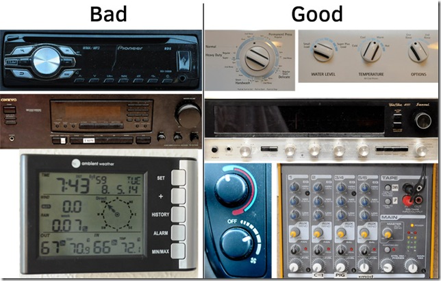
I was thinking about some really good machine interfaces, and some really bad. I walked about the house with a camera. Below are some photo collections of good and bad interfaces around the house.

interface_montage

Good interfaces control devices unambiguously with touch. You should not have to look at the device to know what mode you have changed it to. Really great interfaces, like a light switch, reveal their state by touch.

My switch is almost as good as a light switch. With five states it is hard to tell which state it is in by feeling its position; however, it is easy to change state. Even better, its position is an absolute indication of its state. There is no issue of the Arduino being busy when the state changes, because the state is fixed by the switch. It is not toggled by some transient state.

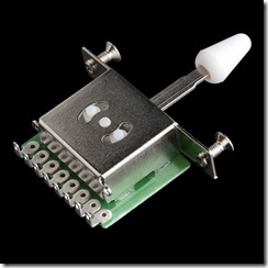
I bought my switch from Sparkfun, and also lifted this product image from them.

5way_product_image_10541-01

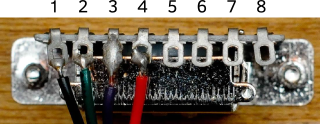
If you can find old rotary switches with detents you can use the analog read function of the Arduino to get all the states with a single pin. In this case, though, I will use three pins to represent the states. I believe it is possible to configure this switch with a  few resistors to represent all its states with a single analog input, but it is more complex to figure out and I am not short on pins. My definition of pins. The ones with wires are the only ones I need to use.

switchphoto_with_pins

With just three digital inputs, the Arduino can read all five switch states. The Arduino’s microprocessor includes built-in pull-up resistors. These are easy to use, but a little bit confusing. A pull-up resistor means that if the pin is not attached to anything, the Arduino will read the pin high.
5state

In the following table I show a Y to indicate how the switch is connected internally. However the ABC column shows what you would read from the pins in the Arduino.

Pos 1 2 3 ABC
1 Y 110 6
2 Y Y 100 4
3 Y 101 5
4 Y Y 001 1
5 Y 011 3
// Define the spins to read the switch
#define pinSwitch1 2 
#define pinSwitch2 3 
#define pinSwitch3 4

unsigned char switchState( void){
  unsigned char state=0, in;
  
  in = digitalRead( pinSwitch1);
  state |= in << 2;
  in = digitalRead( pinSwitch2);
  state |= in << 1;
  in = digitalRead( pinSwitch3);
  state |= in;
  
  switch( state){
    case 6:
    return 1;
    case 4:
    return 2;
    case 5:
    return 3;
    case 1:
    return 4;
    case 3:
    return 5;
  };
  return 0;
}
    
void setup( void){
  pinMode( pinSwitch1, INPUT);
  pinMode( pinSwitch2, INPUT);
  pinMode( pinSwitch3, INPUT);
  digitalWrite( pinSwitch1, HIGH);
  digitalWrite( pinSwitch2, HIGH);
  digitalWrite( pinSwitch3, HIGH);
  Serial.begin( 57600);
  Serial.println( 'Started');
}

void loop( void){
  Serial.print( "Switch: ");
  Serial.println( switchState());
  Serial.print( " ");
  Serial.print( digitalRead(pinSwitch3));
  Serial.print( " ");
  Serial.print( digitalRead( pinSwitch2));
  Serial.print( " ");
  Serial.print( digitalRead( pinSwitch1));
  Serial.print( " ");
  delay( 1000);
}

Monsoon

In the desert it almost never rains. I know, you know. When I lived in upstate New York, in my foolish youth, I bought a motorcycle in the beginning of April. I was anxious to learn to ride. Too bad, because it rained every day for an entire month. Now I live in New Mexico. Two years ago we had not one drop between the end of December and July.

Where you live the weather turns with a unique step. Here, the summer breaks in July when the monsoon comes. Moist air from the Gulf of California and the Gulf of Mexico flow north over the state and give rise to afternoon thunderstorms. It is the most beautiful weather of the year here. The clouds rise miles—literally—into the sky and continuously billow in fractal glory.

Last week I configured my Raspberry Pi computer with its PiCam to take time-lapse video out my back window. The view is to the east over the Sandia Mountains. I took pictures about every six seconds from 10:30 am until dark, around 8:30 pm. The whole day compressed into four and a half minutes. The best video was from July 14, others are below.

It is hard to understand the desert if you have never lived in one. In the picture below you can see what it would be like if Leeds were in Albuquerque. A nation that ruled the world for a few hundred years fits comfortably in the desert southwest.composite

The rest of the videos I created are here, with the most interesting at the top.

July 11

July 13

July 8

July 7

July 10

July 16

July 15

Arduino Flickering Candle

Update December 24, 2013: Mokus refined his code so that the distribution is now well-behaved (nearly normal) and the PSD no longer turns up at high frequencies). The plots and post have been updated to reflect this change. He will push code to the same link as available.


In my previous post on Candle Flame Flicker I describe the statistics of the optical intensity flicker from a candle in terms of the probability density of the brightness samples and in terms of the power spectral density of the brightness. In this article I discuss how to make an Arduino drive an LED to flicker in a way that is statistically similar to the measurements I took on a real candle.

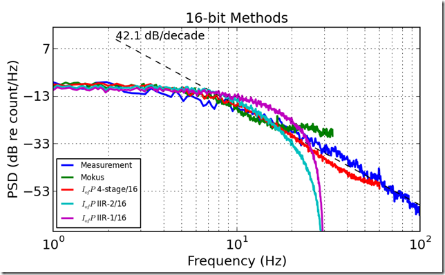
In the measurements I observed the spectral roll-off of the candle to start between about 5 and 8 Hz, and to decline at a nominal rate of around 44 dB for each decade increase in frequency. The 2nd-order infinite impulse response filter is computationally efficient in terms of using a small amount of memory and requiring few calculations. However, the Arduino is not good at floating point arithmetic. On the Arduino, floating point is done in software, has relatively few bits of precision, and is about 4 to 40 times slower than fixed point (integer) math. It is quite difficult to find useful benchmarks. The basic process is to create white noise and then filter it to the correct spectral shape. Afterward, the signal is scaled to have the appropriate variance and offset with a constant to represent the average brightness of the “flame”.

The approach I used was to design the IIR in Python with scipy’s signal module. I specified a 2nd order lowpass Butterworth filter, specifying a cutoff frequency of 8 Hz, and a sample frequency of 60 Hz. I normalized the coefficients to work in a 16 bit integer space, following Randy Yates’ 2010 Practical Considerations in FIR Fixed Filter Implementations, mainly. From a synthesis perspective, there is some prior art. Philip Ching, a student at Cornell synthesized candle noise quite cleverly, though he neither reported nor replicated the correct statistics. A fellow with the handle Mokus did a very, very tiny implementation for a microcontroller with only 64 bytes of RAM. He helped me modify his code so I could compare his statistics, and after adjustment his spectrum and distribution match fairly well. The high-frequency of his PSD looks a little different from the other methods, but these may not be noticeable to the observer. Finally, there was Eric Evenchick’s coincidental post on hackaday. Mokus reported that Evanchick’s implementation has too slow an update rate; I noticed that Evanchick did not report on the statistics he was targeting nor what he achieved. I did not recreate his work to test.

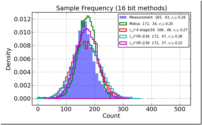
Then, on to the tests. I really was interested in building and comparing statistics from a 16 bit implementation, a 32 bit implementation in both a Direct Form I and a Direct Form II implementation. Indeed, I had great difficulty getting the filters to perform because I kept misdesigning the integer coefficients and overflowing the registers. As I sought a solution to the 2nd-order filter approach, I also created a 4-stage digital equivalent of an RC filter. The 4-stage RC approach was always stable though it needed a higher sample rate and used much more processor power to create statistically consistent results. On the other hand, it has a more accurate spectrum. A comparison of three different 16-bit methods to Mokus’ and to the actual measurements is shown in the figure below. The legend shows the mean, standard deviation, and their ratio to the right of the label. The All my filters did a credible job of reconstructing the histogram.

histo_compare_16

The power spectral density (PSD) of the different methods tells a different story. The Direct Form II 16 bit filter is the most visually appealing of the methods I tried. It rolls off more like the physical data than the other methods, except compared to the 4-stage RC filter. The Direct Form II filter is more computationally efficient.

psd_compare_16

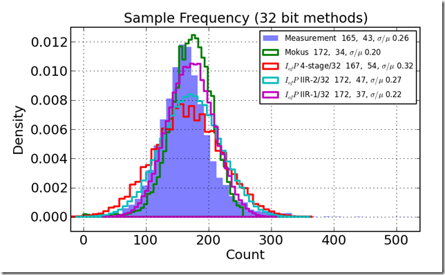
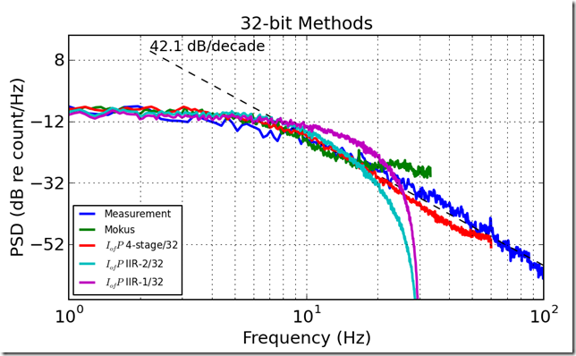
The results for the 32-bit versions show greater variance than the 16-bit versions, but the quality is not markedly better.

histo_compare_32

psd_compare_32


I wrote a proof code for the Arduino UNO both to see it flicker and to test the processor speed—separate parts of the code. The results are that compiling with 1.0.3 resulted in a 4,722 byte program that calculated 10,000 new values in 6,292 ms, or 629 microseconds per value. In theory this could produce a sample rate of nearly 1.6 KHz. Or another way of thinking about this is that the final code uses about 629 us/17 ms or about 4% of the processor capability of the Arduino UNO. That leaves a lot of resources available to do other Arduino work or maybe means it can fit in a cheaper processor.

I have released two pieces of code under the GNU Public License 3, you can get the Python I used for filter design and the Arduino test code at the links. If you want the data, please contact me through the comments and I am willing to provide it.

Candle Flame Flicker

For a project I wanted to make an LED flicker like a candle. I searched for the signal statistics of candle flicker, and I found no data. One student web site suggests that candle flame flicker is a 1/f-type random signal with roll-off of 20 dB per decade increase in frequency. Similar processes are typical for turbulence, so this student’s plan seemed reasonable. However, the student did not discuss whether the signal is Gaussian or not, and did not describe the low-frequency characteristics of the signal. 1/f noises may have a spectrum that follows the 1/f curve to very low frequencies, but because they would require infinite power at f=0 they always have some lower frequency change. I had no data.

Candles aren’t hard to get, and I already had a silicon photodiode for an absorptive smoke density measurement system I’m working on. I also had an analog-to-digital converter (ADC) in an ADS1015 on a breakout board from Adafruit. I made the very simple circuit shown below and attached it to a Raspberry Pi to sample the data. There are a lot more details, but those are later.

circuit

The voltage measured by the ADC is directly proportional to the current through the resistor. The current through the reverse-biased diode is directly proportional to the incident optical power. Very simple. I recorded a minute of data at a low 250 Hz sample rate, and subjected the data to analysis. The setup was a nominally dark room with the sensor a few inches from the flame. I flapped my hand at the candle to get it to flicker while recording.

20131211-04

20131211-06

20131211-12

The first graph below is a histogram of sample values.

dfile_hist

The histogram is about normally distributed, but the right-hand tail is not Gaussian; it is too fat. In other words the candle is occasionally much brighter than normal. The time series (below) shows the same properties. There are clearly visible large excursions.

dfile_time

For human eyes the candle’s flicker will be well represented if the frequency spectrum of the flicker and the distribution of the flicker approximately match a natural source. The spectrum below can be thought of as an average brightness (the peak at the left), a flat spectral region out to about 4 Hz, and then a 1/f-style roll off at 44 dB per decade.

dfile_psd

Numerically, we have the recipe for a flickering candle:

  • Samples should be normally distributed with a standard deviation equal to 0.25 of the mean.
  • The power spectral density of the signal should roll off at about 40 dB per decade with a 3 dB cutoff frequency around six cycles per second.

To make this work on the Arduino using the pulse-width modulated outputs, we can further constrain the problem:

  • The maximum value cannot exceed 255 counts—or make the limit that the mean plus two standard deviations is 255.
  • From this, we can derive that 2s+m = 255, use the fact that 0.25m=s to find that the mean m=170 and the standard deviation is about 42.
  • A sample rate of between 30 and 120 Hz should be more than adequate to satisfy the Nyquist criterion for human vision (see Wikipedia).
  • Values may not go below zero or above 255
  • A second-order infinite impulse response (IIR) filter has a roll-off of 40 dB per decade

If we can find a numerically efficient way to generate a time-series of Gaussian random variables inside the Arduino, filter them with a 2nd-order fixed-point IIR, scale them (if needed) then we should be able to make a flickering candle.

Unfortunately, I have failed repeatedly to get a stable fixed point IIR filter. The cookbook solution specification above should be easy to implement, but I have not found it so. A better solution will have to wait for another post.

Raspberry Pi Character LCD Degree Symbol

It is inevitable that you will want to write the degree symbol to your 16×2 character LCD once you have it wired to the Pi. My son wired it up, and then wanted to display the degree symbol. In the past I have solved that problem for the Arduino using the Adafruit character LCD Arduino library createChar() function. Relatively painless for the Arduino. Unfortunately, the Adafruit LCD library for GPIO not using i2c does not have an equivalent of the createChar() function. Sad.

The solution turns out to be easy. You rely on the fact that the LCD already has a degree symbol built in, and then use the write4bits() function to display it. There are other characters available, I found mine here. Here is our code.

# This is the process of importing the Adafruit library
adafruitCharLCDPath = "/home/pi/pylib/AdafruitPy/Adafruit_CharLCD"
if not adafruitCharLCDPath in sys.path:
    sys.path.append( adafruitCharLCDPath)
    from Adafruit_CharLCD import Adafruit_CharLCD

os.system('modprobe w1-gpio')
os.system('modprobe w1-therm')

temp_c = 23.1
temp_f = 32. + temp_c*9./5.

lcd = Adafruit_CharLCD()
lcd.clear()
lcd.message("temp C")
lcd.write4bits( 0xDF, True)
lcd.message(": %.1f\n"%temp_c)

lcd.message("temp F")
lcd.write4bits( 0xDF, True)
lcd.message(": %.1f"%temp_f)


That Noisy Fan–Calibrated Measurement

I am working with the freetronics microphone module, which is described as having a sensitivity of “-40 dB typical”—let us assume it is dB (SPL) referenced to 20 micropascals root mean square (rms) at 1 KHz. When I think of an electronic element’s sensitivity, though, I’m thinking volts per micropascal and this is not provided.

The microphone’s schematic suggests the SPL measurement is the rms average over 3 milliseconds, and that the signal is proportional to rms pressure level. This suggests a log scale for display (a change from previous work).

The upshot is that the fan generates about 62 dBA; but to get that conclusion, I had to perform a spectral correction to match measurements from a more calibrated sensor.

sound_level_dba

Remember that I made the measurements with the RIMU data logger I built. That data logger has a digital low-pass filter on the microphone SPL. The low-pass filter has much too slow a response, but the basic result is OK. The RIMU, shown in the next picture, is the instrument.

20130803-24

I borrowed an SPL meter from my father (thanks!). It is, unfortunately, a C-weighted measurement, measuring in dBC. The C-weighting is occasionally a very useful measurement of sound level. Most measurements are done A-weighted, which is similar to human hearing. My challenge is to convert a measurement made with an unweighted microphone in arbitrary units to A-weighted measurement in dBA. The answer is to take a measurement with the instrument in dBC, and record the sound a with a sound recorder, figure out what converts C-weighting to A-weighting for this signal.

20130803-25

In the spectra below you can see that the spectrum recorded without weighting, by the Zoom recorder. I then applied an A weighting and a C weighting. What’s important is the conversion between the rms value for A and the rms value for C, which is a 6 dB correction in one case, and a 13 dB correction in the other.

fanandwater-psd


fanonly-psd

So, to rehash the steps

  • Record a sound level with the RIMU
  • Measure a reference condition in dBC with the SPL
  • Record a 15 second period with the Zoom
  • Apply the A weighting to the Zoom record
  • Apply the C weighting to the Zoom record
  • Find the difference in dB between the A and C weighted records
  • Assume the dBC weighting corresponds to the measurement made with the RIMU, and adjust the RIMU values so that they match the C-weighted measurement from the SPL
  • Apply the C-to-A correction to the RIMU measurement.

Pretty epic pain, but at least I have the measurements. In the future I will recode the RIMU to take short A-weighted and C-weighted snapshots, and then calibrate the RIMU on the dBA record. Look for a follow-up post far in the future.

Arduino Analog Sample Rate

The Arduino Uno is not the ultimate signal processing machine, but it can do some light duty work on burst data. I had trouble finding the maximum sample rate the Uno can support, which is totally critical for most kinds of work.

With native prescale

  • Samples, type casts into floats, and stores in an array at about 8929 Hz, or 112 microseconds per read-and-store
  • Samples and into stores into an array of unsigned integers (16 bit) at about 8930 Hz, or 112 microseconds per read-and-store

We can step this up quite dramatically by setting the prescale set to 16:

  • Samples, type casts into floats, and stores in an array at about 58600 Hz, or 17 microseconds per read-and-store
  • Samples and stores into an array of unsigned integers (16 bit) at about 58606 Hz, or 17 microseconds per read-and-store

Pretty close to a 60 KHz sample rate, more than adequate for audio sampling. Of course, the Arduino doesn’t have enough memory to be a serious audio processor, but it is pretty goood.

The forums discuss this, and arrive at a similar conclusion.

#define NSAMP 5000

void setup(){
  Serial.begin( 57600);
 
  float array_float[ NSAMP]; // float
  unsigned int array_int[ NSAMP]; // 16 bit
  unsigned long int micsbegf, micsendf, micsbegi, micsendi;
 
  for( int i = 0; i &lt; 2; i++){
    if ( i == 1){
       // Set prescale to 16, and retry
      sbi(ADCSRA,ADPS2);
      cbi(ADCSRA,ADPS1);
      cbi(ADCSRA,ADPS0);
    }
    
    // Record floats (extra time for type conversion presumably)
    micsbegf = micros();
    for( int i = 1; i &lt; NSAMP; i++){
      array_float[ i] = (float)analogRead( A1);
    }
    micsendf = micros();  
    
    // Record floats (extra time for type conversion presumably)
    micsbegi = micros();
    for( int i = 1; i &lt; NSAMP; i++){
      array_int[ i] = analogRead( A1);
    }
    micsendi = micros();  
   
    if( i == 1){
     Serial.println(&quot;with prescale set to 16&quot;);
    } 
    Serial.print(&quot;recorded &quot;);
    Serial.print( NSAMP);
    Serial.print(&quot; float samples in &quot;);
    Serial.print(micsendf - micsbegf);
    Serial.println(&quot; usec&quot;);
    
    Serial.print(&quot;recorded &quot;);
    Serial.print( NSAMP);
    Serial.print(&quot; unsigned integer samples in &quot;);
    Serial.print(micsendi - micsbegi);
    Serial.println(&quot; usec&quot;);
  }
}

void loop(){
  delay( 10);
}